
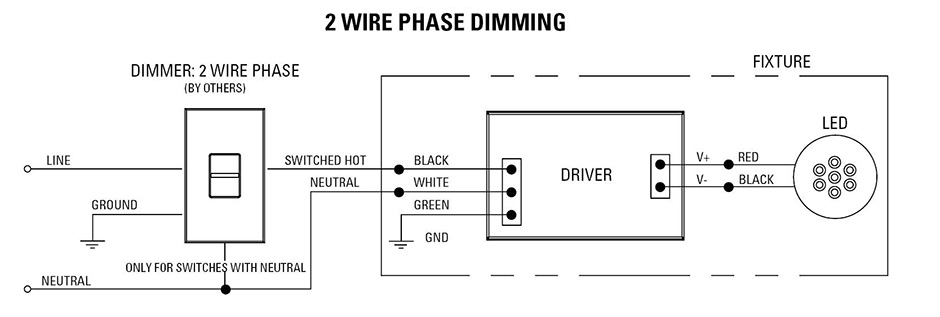
Phase Dimming Wiring Diagram
Buy cree zrlkv k led troffer. A wiring diagram is a streamlined standard pictorial representation of an electrical circuit.

Wiring Diagrams Part 1 Zaniboni Lighting
In the diagram below a 2 wire nm cable supplies power from the panel to the dimmer box.
Phase dimming wiring diagram. Switch wiring shows the power source power in starts at the switch box. Erp offers dimmers with all three dimming options but we do not recommend using more than one dimmer at the same time. Maximum load 1 gang 2 gang 3+ gang
When wired without a neutral, loads may appear dimmer. Each component ought to be placed and connected with other parts in particular way. Check out our wiring wizard for step by step instructions videos and wiring diagrams including 3 way for installing a dimmer.
All usai elv dimming options are for use with 120v only. Forward and reverse phase dimming forward and reverse phase dimming forward phase (leading edge) controls. 200 rome court fort collins, co 80524
Elv dimmer led driver hot/line black common/neutral white yellow white black reverse phase elv wiring diagram line voltage 120v 120v output led load low voltage dc powered by ltf®. Control4 home automation wiring diagram. Philips evokit led 2x4 and 2x2 the philips evokit is designed for installation in a wide variety of 2x4 and 2x2 indoor fluorescent based fixtures in horizontal applications.
Dimmer led driver hot/line black common/neutral white white black triac dimming wiring diagram line voltage 120v 120v output led load low voltage dc wiring diagram powered by ltf ® l.t.f, l.l.c. It installs in a standard back box using typical wiring standards and communicates to the control4 system. Switches with two pilot lights.
The control4 forward phase dimmer operates independently or as part of a control4 home automation system. A typical forward phase wiring diagram is shown below: This can result in having to pull additional wire on remodel projects.
A typical reverse phase wiring diagram is shown below: Power consumption 450mw load types and ratings supported load types incandescent, halogen, magnetic (iron core, inductive) low voltage (mlv) transformers, forward phase dimmable fluorescents, compact fluorescents, and leds. Usai lighting reverse phase dimming solutions.
Leading edge phase control (le) dimming wiring diagram le phase control dimmer switch dimmed hot (black typical) electrical panel hot (black typical) 120v neutral (white) ground ground led pendant, sconce, or ceiling lutron 253p or equal (1) pendant per switch up to (8) ceiling mounts per switch or other lutron compatible controls refer to manufacturer for additional. The design, reverse phase dimmers generally require a neutral wire for operation. Watt troffer with 75, life hours.
A 2 wire switch leg is pulled from the switch to the nearest light below is a line. Usai lighting forward phase dimming solutions. Electronic low voltage (elv) dimmer wiring diagram examples of elv dimmers:
Three way wiring diagram 0 hunt control systems, inc. These instructions will probably be easy to grasp and implement. It installs in a standard back box using typical wiring standards and communicates to the control4 system using a wireless connection.
Wiring diagram will come with numerous easy to follow wiring diagram directions. Evokit step dim wiring diagram line 1 s2 line s1 step dim 16aregulations and electrical codes. Dimmer buzz, lamp flicker, interaction between circuits or radio frequency interference (rfi).
This arrangement is provided for easy reference when dealing with a circuit wired in this arrangement. It's intended to assist all the average consumer in building a proper system. All usai triac dimming options are for use with 120v only.
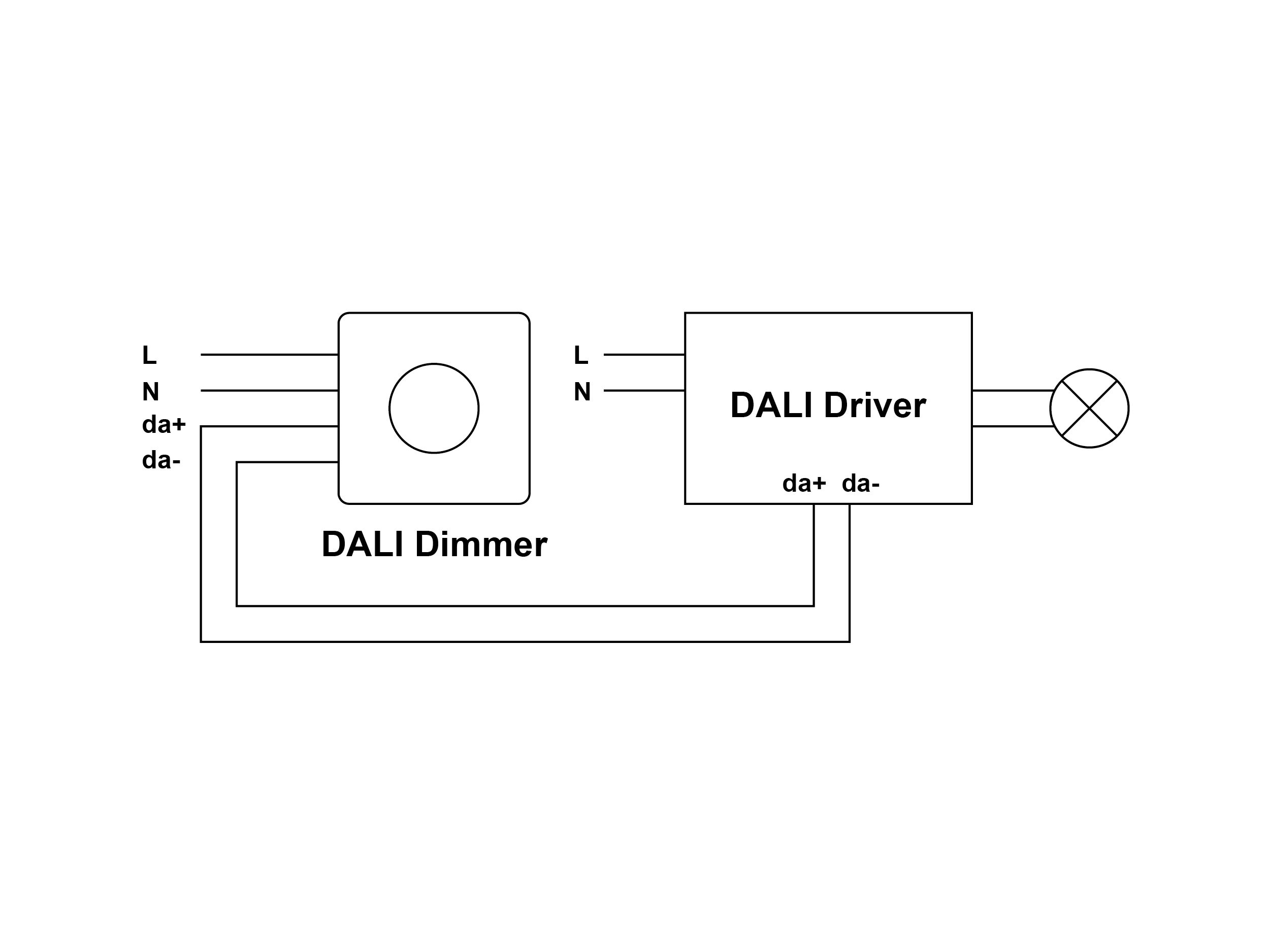
201 north service road, melville, ny 11747 tech line: Wiring diagram single loop smart lighting control panel, replace traditional dimming knob, can be applied to small space of lighting control.

0 10V Dimming Wiring Diagram Wiring Diagram And Schematic Diagram Images

Electrical Circuit Diagram For A Typical Scr Based Light Dimmer Circuit Diagram Images

Low Voltage Led Dimmer Wiring Diagram Reverse Phase Dimming Solutions Usai Incandescent
Low Voltage Led Dimmer Wiring Diagram / Low Voltage Led Dimmer Wiring Diagram Wiring Diagram


Low Voltage Led Dimmer Wiring Diagram Wiring Diagram Schemas
Low Voltage Led Dimmer Wiring Diagram Wiring Diagram Schemas

Forward Phase Dimming Solutions USAI
Phase Cut Dimmer Wiring Diagram
31 0 10 Volt Dimming Wiring Diagram Worksheet Cloud

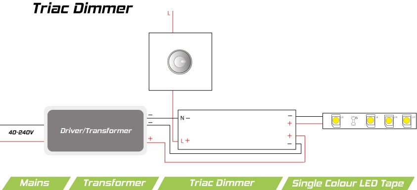
30Watt Dimmable LED Transformer (TRIAC phasedimming)

35 How To Read Schematic Diagram Wiring Diagram Database

Low Voltage Led Dimmer Wiring Diagram Wiring Diagram Schemas
Wiring Diagram For Led Dimmer Wiring Diagram Schemas

Lighting KnowledgePhaseCut DimmingKaoyiLighting Control, Smart Lighting Control
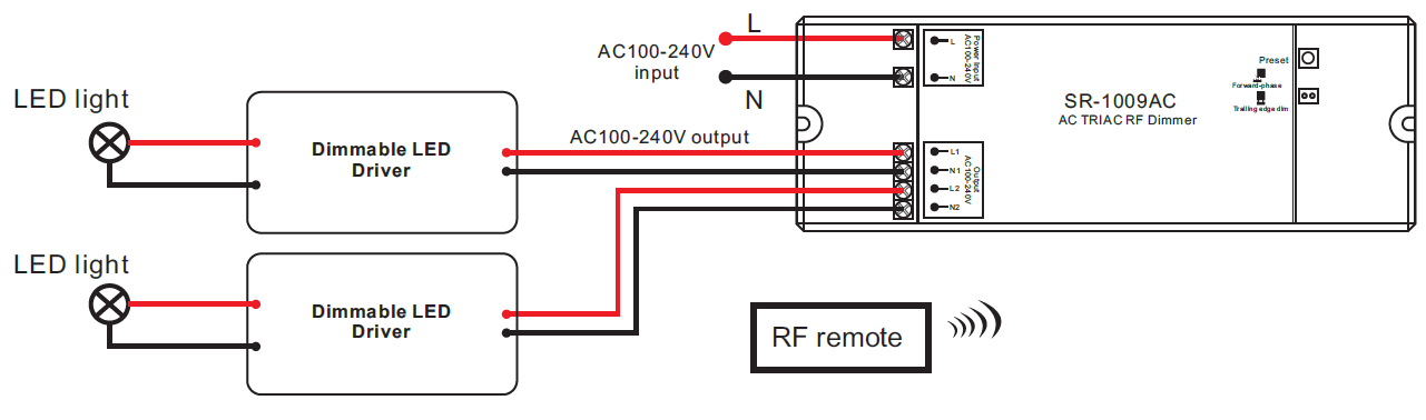
2 Channel AC Triac LED Dimmer Switch With RF Control SR1009AC

Wiring Diagrams Part 2 Zaniboni Lighting
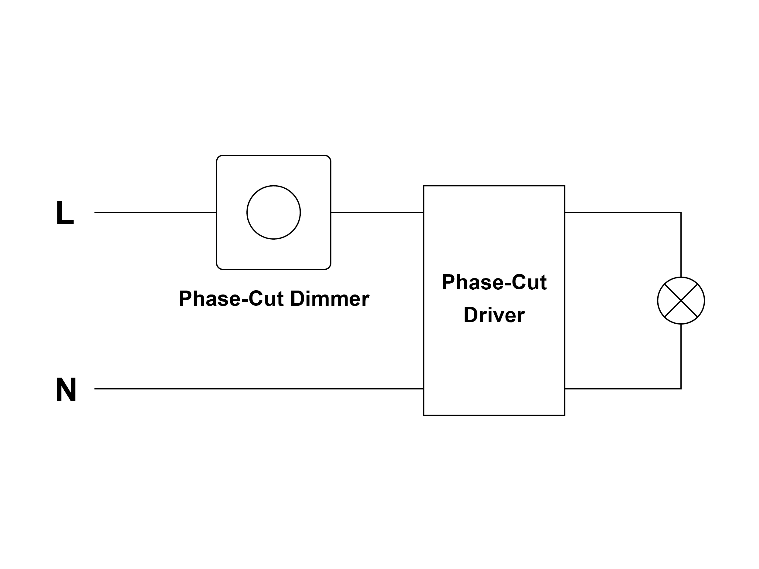
Lighting KnowledgePhaseCut DimmingKaoyiLighting Control, Smart Lighting Control
Sunricher AC Wall Dimmer Phase Cut Triac RF Push Switch, View ac wall dimmer, Sunricher Product

TRIAC Dimmer Module LED receiver for phasedimming control
